
TMWR Series Metric Wear Rings
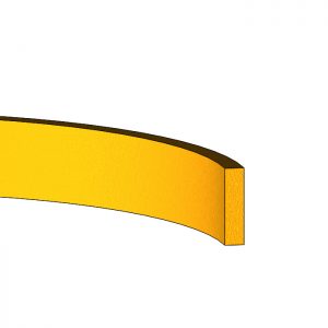 The TMWR wear rings are precision machined to guide a rod or piston to avoid metal on metal contact in dry and lubricated applications. A gap is intentionally added to the wear ring to allow fluid flow to and from the seal gland and prevent pressure trap or hydrolock between the seal and wear ring. In the case where the cut ends of the ring touch due to the high thermal expansion of PTFE, an optional radius groove is added on both ends to continue to allow fluid flow.
The most common cut is an angle (scarf) cut, but TMWR wear rings can be ordered with a butt, step, or zee cut.
Advantages:
- Low Friction
- Improve Concentricity
- Prevent large extrusion gaps that cause seal failure
- Prevent Galling
Applications:
- Shocks and Struts
- Mobile Hydraulic Cylinders
- Pneumatic Piston Cylinders GAP
- Agriculture Equipment
- Hydraulic Valves and Pumps
- Filling Machines
- Testing Machinery
Technical Data:
The T-LON® PTFE wear ring compound and width determines allowable radial load and velocity ranges
- Velocity: Up to 15 m/s
- Radial Load: See Calculation (Max velocity and radial load cannot be used together)
- Temp. Range: -240°C to 285°C (Above 120°C, compressive strength decreases reducing radial load capability)
Most Common:
F BRONZE FILLED PTFE (“21” or “22”)
- High compressive strength/wear resistance (More bronze content improves these properties).
- Low abrasive features
GLASS/MoS2 FILLED PTFE (“31”)
- Good wear resistance for parts with rougher surface finish
- More chemical resistant and used in applications with minimal to no lubrication
Calculating Ring Width using Bearing Stress Calculation:
Width (mm) = (F x FS) / (ID x C)
- F = Radial Force (N)
- FS = Factor of Safety (2 Min. recommended)
- ID = Rod Diameter /Assembled Ring ID (mm)
- C = Wear Ring Compressive Strength (MPa, See Table 1)